Monday, April 30, 2012

Data System Part 4

In order to connect to the EV04 data system using my computer, the data system comes with a USB cable that has a binder connector which connects to the system and a male Type A USB connector which plugs into the computer.  This works fine but the data system in my car is not going to be easily accessible and I didn't like the idea of having a loose cable in the car.  So I did some searching on the internet and found a panel mounted USB adapter.  The one pictured below happens to be Type A to Type B but I have a Type A to Type B cable so the adapter works fine for what I need.  With this adapter in place, the USB cable from the data system will be permanently plugged into the adapter and I can then plug the computer into the data system using the Type A to Type B cable.


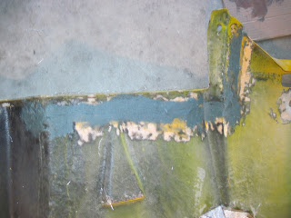
Here is the adapter installed.  Unfortunately I didn't do a very good job of cutting the hole for it so I covered up gaps with some black electical tape.  The tape shows up a lot more in the picture versus in person -- which is a good thing. :>)


One challenging thing about installing a data system in a small formula car is doing something with all the cables.  More sensors means more cables and they are never the exact length that you need them.  This is one reason why I installed the system where I did.  I figured it would give me enough room to store the cables.  Of course I also need to cover all of those cables up and the fiberglass cover that came with the car was not going to do the trick.  So I decided to make a new cover out of aluminum.  But first I needed to get the shape and the easiest way I could think of to do that was to use a thin piece of 1/2" steel scrap that I could easily bend to the shape that I wanted.


After I had that piece made, making the aluminum piece was pretty simple.  It will also serve as a nice sturdy piece that the seat can rest up against.


The next data system task was installing the display on my steering wheel.  I'm using the steering wheel that I had in my Formula Vee and since I used an AIM system with the same type of display in that car, the steering wheel was already cut for the display.  Also, the person I bought the EV04 system from had made a bracket to hold the display and that worked well too.


I was also able to purchase a used AIM Smarty Cam that will not only give me video but it will also give me data overlayed on the video which will be a great learning tool. 


I also needed to install the GPS sensor that came with the EV04 system as well as the GPS sensor that came with the Smarty Cam.  The will work through fiberglass so I figured the easiest thing to do was to place them on top of the ECU and secure them with some velcro.


The only that is left for me to do on the data system installation is connect the brake pressure sensors and  the fuel temperature sensor.  I ran out of patch cables so I had to order a few more.


Monday, April 23, 2012

Data System Part 3

I didn't make a post last week because I was some friends of mine at the first 2012 F1600 series races at Virginia International Raceway two weekends ago.  That was the first time I had been to one of those race weekends and I'm really glad I went because I learned a lot and I got to see for myself that it really is a great series.  The young guns (16 to 18 yr olds) really showed their stuff and were the class of the field although some slightly older drivers were knocking on their door!

This past weekend I didn't get as much done as I would have liked because I unfortunately got sick and I was just not that motivated to do much with a 102 degree fever!  But I did get a little bit more done on the data system and I finished installing the shock sensors.

For the rear shock sensors, I bought a couple of potentiometors for less than $20 each and I kept the old AIM patch cables that came with the car and cut off the female ends off so that I could solder them to the potentiometors.  I would then glue servo arms to the shafts and glue some "L" pieces that I made to the sides so that I could fasten the potentiometers to the rocker arms.  Well, gluing the arms to the shafts worked fine but gluing the "L" pieces to the sides didn't and I had to make brackets that were a little more elaborate.


After soldering the connector to the potentiometer, I used shrink wrap to protect the wires and then put epoxy over the area to keep any moisture away from the wires plus it should help prevent the wires from getting pulled away from the potentiometor.  I mounted the potentiometors the same way as I did on the front shocks.


The only other sensor that I was able to install was a Fuel Temp sensor.  I already had the sensor, I had the fitting, and there was an empty channel on the data system, so I figured I might as well use them. 


The only sensors that aren't mounted yet are the wheel speed sensors and I obviously can't install those until I have suspension on the car.  I just need to do a little more bodywork before I can install the suspension.


Monday, April 9, 2012

Data System Part 2

The next type of sensor that I'm tackling is the shock sensor or suspension travel sensor.  However, I'm not installing the typical type of sensor because I'm trying to save a little bit of money.  The normal shock sensors are easily $250 each so for four shocks that would be $1,000.  I had a couple of AiM rotating potentiometer sensors which I used for throttle and brake in my FV so I'm going to use those for the shocks.  Plus I'm going to use some very inexpensive rotating potentiometers for the other two shocks.  The internet is a very powerful tool and I got the idea to use these sensors from James Hakewill (http://www.jameshakewill.com/).  James is an engineer and an open wheel racer and he has posted some really great technical information on his website. 

Here is a pic of one of the AiM rotating sensors that I described above.  However, it didn't come with the arm that is on it.  This is something that is used on radio controlled vehicles, like cars, planes, and helicopters.  In fact, I bought a number of trick little pieces from the local hobby shop for this purpose.


You can see that the sensor is mounted on the rocker.  I again just used 10-32 nutcerts to accomplish this.  The rod and the piece that the rod is going through were again from the hobby shop and this will give me lots of flexibility in regards to adjusting the position of the sensor arm on the rod.  It might be hard to see in the picture but there is a set screw on top of the rod that can be loosened to allow the rod to slide through the hole.

For the fixed position side, I simply took a piece of 1/16" steel and drilled a hole in it so that it could be mounted to the shock bracket using the shock mounting bolt and then I bent it at a sufficient angle so that the rod was parallel to the shock.  Again, the rod, the rod end, and the hardware, were purchased from the hobby shop.


And here is a pic of the complete assembly.


Although it took me a while to figure out how to mount the sensor, it was a fairly easy installation.  Only three more shocks to go! 

Tail Section Part 4

In the Tail Section Part 3 post I stopped with the cutting of the tail section in order to get it to fit to the side panel better.  After laying some fiberglass matt over the gap while it was on the car, I needed to fill the gap on the inside.  I knew I wanted to use short strand fiberglass filler but I wanted to strengthen it a little bit more so I simply cut some fiberglass matt into very short strands and then mixed them into the filler.  You can buy long strand fiberglass filler but I have found that to be very hard to work with.


And here is a pic of the filler spread into the gap. 


After sanding the filler, I then layed fiberglass matt and then some cloth over the matt to give it even more strength. 

The next part of the tail section that I needed to tackle was the top of the tail behind the roll bar.  The right side is fine but the left side sticks out in the air stream too much.


So it was time to cut it up again -- which I did!  Of course, after cutting it I needed to fill in the gap.  In my first attempt, I used flashing to try to get the shape that I wanted. 


Unfortunately that didn't work as well as I would have liked so I started over again.  This time I went back to using the two part expandable foam. 


This worked much better and I was able to sand it to the shape that I wanted.  I'm in the process of laying bondo over it but below is a pic of how it looks right now.


So I'm now in the process of laying bondo, sanding, laying bondo, sanding, etc. etc.  I don't planning on documenting this whole process but I will post some pics of the tail just before it goes to paint.

Monday, April 2, 2012

Data System Part 1

The data system for this car is something that I'm really forward to using.  I have taken a number of online data acquisition classes taught be John Block of Autoware (http://www.auto-ware.com/) and John really helped me understand the importance of data acquisition.  I have actually been able to use some of the things that I have learned when I am racing online on iRacing as well.  The AIM EV04 system has an internal three axis accelerometer which will give me longitudinal, lateral, and vertical g's.  It will also give me predictive lap times and has a GPS that can be used to draw track maps so that I can look at data at a specific point on the track.  It also has an ECU connection so a lot of the data I gather will come from the ECU.  Some of the data that will come from the ECU are rpm, throttle position, oil pressure, oil temperature, air/fuel ratio, and fuel pressure.  The data system also has a wheel speed input as well as 5 analog inputs.  I have actually expanded it so that I will have 9 analog inputs.  I plan on having 2 brake pressure sensors (front and rear), 4 shock sensors, a steering sensor, and maybe a fuel temp sensor.  I have also added a data hub to the system which the 4 channel expansion unit is plugged into but I also have an AIM camera (called a SmartyCam) that will plug into the data hub.  The video from the camera will have data overlayed over the picture -- this will be a great analytical tool.  Ok, now that I have explained most of it, the pic below shows the system.  The basic AIM EV04 unit is on the bottom left, the data hub is mounted above it, and the channel expansion unit is mounted on the right.


I have been (and will be) working on installing sensors in between working on the tail section.  I talked about this before but the car came with a steering sensor installed in the steering rack.  Here is a pic of that sensor installed.


I recently installed the brake pressure sensors, and figuring out where to put them was quite the challenge.  But first, I purchased a couple of brake pressure manifolds from Veracity Data.  These are really nice pieces and the brake fluid flows through them but there is a place for the sensor and there is also a bleeder valve at the top which will allow me to get rid of any air that may be stuck in the line there.  Here is one installed in the front bulkhead.


The thing that is missing from the picture above is the front sway bar and I really had to do some thinking and measuring in order to figure out that I could mount these in this area.  I actually bought a number of brake line fittings that I found out wouldn't work because they extended away from the manifold too far.  That is why I chose to go with the banjo bolt fitting on the left side of this manifold.  Here is a pic of both manifolds installed but the actual brake lines are not attached yet.  The left side manifold is for the front and the left and right front brake lines will attach to the tee fitting.  The rear brake line will attach to the 90 degree hose fitting that is attached to the right manifold.


And here they are with the sway bar mounted.


Tail Section Part 3

I don't have as much to report on the tail section as I would like but I have made a little progress.  The good news is that I put the tail section on the car after fiberglassing the right side and there were no clearance issues.  Yeah!  Unfortunately there was a divet in the bubble.  I can only surmise that this was caused because I couldn't fiberglass over the foam while the tail was on the car and when I put the tail on the car, it changed shape a little bit.  In order to fix it, I cut slits in the bubble and taped some soft foam to the engine so that it would push out on the bubble a little bit.


I could then fiberglass over the slits and then I also fiberglassed on the backsides of the areas that I filled in with fiberglass matt and set the tail back on the car without the foam in place so that it hardened on the car which allowed it to take a natural set.


Now I just need to put bondo over it -- not like that isn't a lot of work in itself! 

Another issue that I needed to address with this tail section is that the right side wasn't meeting up with the side panel very well. 


In order to fix this, I again needed to destroy it a little more.  I cut a large upside down "L" slit in it so that I could line up the edge of the tail section with the edge of the side panel.  I could then fiberglass over the gap.  Again, I did this while the tail was on the car.


That is as far as I gotten but I can now fiberglass on the backside and it won't be long before I can start spreading bondo and going through multiple stages of sanding in order to prepare it for paint.