Monday, May 28, 2012

The Home Stretch!

I'm really pushing to get the car finished for a test day on June 8th and possibly a regional race that weekend.  So I took Friday off from work and since today was a Memorial Day, I was able to spend four days in the garage -- which turned out to be very hot!!  I made a lot of progress but unfortunately material for the blog suffered because I forgot to take as many pictures as I have taken for previous blog entries.  But here ae a few pics to at least show the progress that I have made.

With the help of my beautiful wife and crew (Terry) I was able to get the front suspension on.  It was a little difficult because of the suspension mounting within the bodywork in a number of spots and it is hard to get to those mounting points inside the car.


I was able to get both wheel speed sensors intalled in the front of the car.  The car came with one installed and I just copied the brackets to make brackets for the other side.  The sensor detects a magnet that is mounted on the inside of the hub and you input the tire size in the data system software as well as the number of magnets that the sensor is supposed to detect and the software can then determine the miles per hour.


I was also able to make my first gear change!  It probably took me about 5 times longer than it should have but at least I learned a lot and am confident that I will get better and faster at changing gears.


I was also able to get the rear suspension on the car and the rear axles.  There are CV joints on either side of both axles and I re-packed those with new grease.  I ran into some difficulties here in this task and had to replace a couple of CV boots but I figured everything out. 

Before putting the car back down on the ground I wanted to install some screens to keep debris out of the radiators.  I used some hardware cloth from Home Depot and decided to mount them to the ducts that sit over the radiators and mount inside the side pods. 


In order to give the screen more support, I mounted a piece of 1/2" wide aluminum along the bottom of the screen to hold it to the bottom of the sidepod.


Finally it was time to put it back on the ground!!  I used my engine hoist to lift the car and then lowered it on some stands just higher than the legs of the engine hoist. 


I was then able to work each end to the ground with my quickjack and here she is on the ground!


Next, I needed to make a seat.  Even though a fiberglass seat came with the car, all the things that I changed in the cockpit made it very difficult for me to use it.  Plus, I also wanted to try making a bead seat -- which is basically a bunch of small styrofoam beads that are held together with resin.  There is lots of information on the internet about how to make a bead seat but the first thing you do is determine how many beads you need by putting a bag of beads in the car and sitting it to determine if that is the right amount of beads.  However, before you can do that, you need to line the inside of the cockpit with cardboard to prevent the beads from getting in between the chassis tubes and other nooks and crannies.  Also, you tape some thick plastic over the cardboard and other areas to prevent the bag of beads from getting punctured.


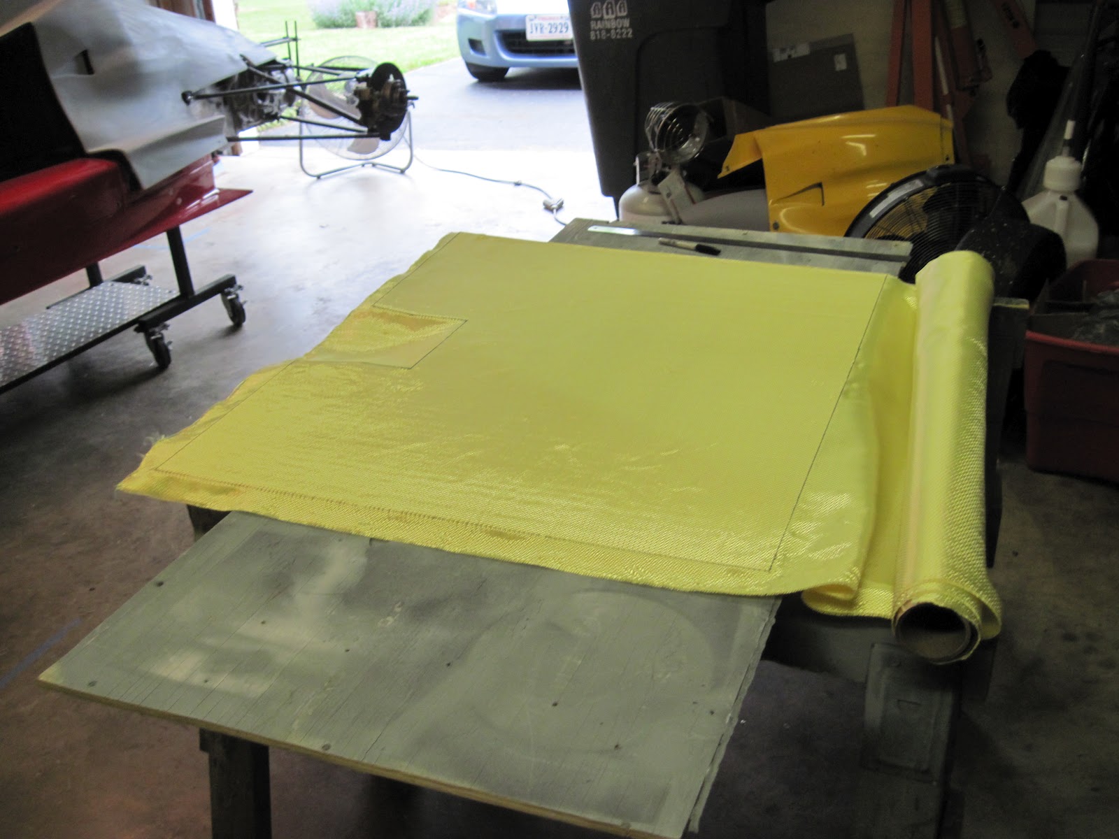
The kit came with 12 gallons of beads and I ended up using 7 gallons.  The bag is a vacuum bag and you hook up a shop vac to it to suck the air out of the bag.  You can do this before the resin is mixed in with the beads to make sure that the amount of beads is sufficient.  After that is done, you mix resin in with the beads and put the bag back in the car.  You then get to sit in the car for 45 minutes with the vacuum running for 45 minutes.  The resin actually doesn't fully set in the time period and it is left in the car for 12 hours.  Again, Terry helped me through this whole process and we decided to do this last step late in the evening so that the seat could set overnight.  When I looked at the seat after I got out of the car, I noticed that some of the aluminum fuel cell cover wasn't covered by the beads so the next morning I cut a section of the bag away from that area and mixed a small amount of beads and resin in a food storage bag so that I could place them in that part of the seat.  I put a kitchen garbage bag over that area and sat in the car for another 45 minutes.  I had already started trimming the seat when I took this picture but you can see the rectangular area where the patch work was performed.


And here is a pic of the seat in the car with most of the trimming done.  Next, I'm going to cover it with gaffers tape and that will ensure that all of the beads are kept in place.


The instructions say to remove all of the bag but there are so many folds that go into the beads that I'm just going to leave the bag there and tape over it.  You can also glue material over the seat but the taping is obviously the quickest method.  It looks like it will work out well though!


Monday, May 21, 2012

Fire Exinguisher

In another post, I mentioned that I had to order a new fire extinguisher because the one that came with the car had a slow leak.  At first I ordered a mechanical fire extinguisher but I couldn't get that one too fit due to the overall length and the handle was getting in the way of other things.  So I sent that one back and exchanged it with the electric version.  It is actually a really nice system that has its own control panel which has batteries to activate the extinguisher if needed.  You can also flip a switch to arm and de-arm the system.

Here is a pic of the extinguisher installed.  You can see the extinguisher tubing and the electrical cable mounted to the extinguisher.


And here are pics of the control panel which is velcroed to the bodywork and the button that I would push if there was a fire.


I did not take pics but there is a nozzle in the cockpit area and one in the engine bay.

Due to the straps and latches that hold the extinguisher in place which my feet could hit getting in and out of the car, I decided to make an aluminum cover.  In order to figure out the shape of the cover, I again turned to using the thin 1/2 inch steel to get the shape.


When bending the aluminum, I layed the steel template next to the aluminum on my metal brake so that I could match the angles.  Take a note of the metal brake that I'm using in the pic below.  I bought this from Harbor Freight many years ago for something like $20.  It certainly isn't an optimum piece of equipment but for tasks such as this it actually does a decent job.


Here are some pics of the cover installed.


Unfortunately, I got in the car and found out that my calves were hitting the cover!  And after looking at these pictures, I have realized why -- the cover is much higher than the battery and the template was not that high.  Oh well, I can probably modify it but I can also drive the car without it so this is probably something that I will re-visit after the first test day. 

Undertray Part 2

Continuing on with the undertray, I was able to fiberglass the edges during the evenings last week.  I used a very light fiberglass cloth and put two layers on each edge.  I could only do one edge at a time because I had to let the resin harden and trim off the excess cloth before moving onto the next edge.  Unfortunately bubbles are hard to avoid when trying to wrap around such sharp edges unless you are vacuum bagging -- and I don't have the vacuum bagging equipment.  The first side that I did had more bubbles then I would prefer so I used a fiberglass filler that you can mix in with the resin when laying up the remaing edges.  The cool thing about fillers is that you can add a little bit at a time to get the consistency that you want and then it will harden at the same rate as the cloth after you have layed it on top.  Here is a pic of one of the sides with the filler -- which is white.


I also fiberglassed the top side and I used a heavy piece of fiberglass cloth and then put a light layer on top of that.


After the resin hardened, I put a layer of "icing" which is basically a finishing puddy that is much easier to spread then the standard bondo.  It is mainly used for filling in pinholes and other small imperfections but it worked well here because the light fiberglass cloth has a really tight weave and it is a flat surface so it was especially easy to spread it.  After the first application I sanded it down with 180 grit sandpaper and then applied another layer and sanded again.  It was now time to mount it to the car so that all the holes would be drilled prior to paint.

I'm mounting the undertray to the side pods with a couple of strips of aluminum.  I'm not ecstatic about this approach but it will work for now and I probably won't use the large washers when I permanently mount it so that alone will make it look better.  Plus I think the aluminum will look a lot better after it is painted red.  It is something that I can easily change later if I want.


After I got the front secured, I needed to come up with a way to support the back.  At the last race I was at, I noticed that some cars used metal straps to do this.  I had some thin 1/2 inch wide steel so this is what I decided to use.  However, it was a litle bit of a challenge to figure out the exact length and the bends so I could another piece of 1/4" plywood that was only about 4 inches thick and put this where the undertray would go.  This allowed me to extend the steel past the plywood and helped me figure out where to bend the steel to get the shape and length that I wanted.


And here is a pic of the undertray mounted -- and I dropped it off with my paint guy today!


Monday, May 14, 2012

What's Taking So Long?!

I have actually heard this question a few times and frankly I ask myself it sometimes.  :)  Well, all I can say is that it is amazing how long some things take.  For example, I really didn't like the zeus fasteners that came with the car and most of them were on the tail section.  So, I removed all of those fasteners and filled in all the holes so that I could install the camloc fasteners that I want to use.  I used these on my FV and I just really like how they work.  Here is a pic of one installed in the nose of the Formula F.


However, the difficult thing about all of these fasteners is that they come in different sizes.  So, in order to determine what to order, I first had to measure the thickness of the bodywork in all of the fastener mounting points and calculate the length of the fastener.  This took quite a long time in itself (maybe 4 hours) and I really won't know if I got it right until I receive the fasteners and receptacles that I ordered which should be here this week.

The brakes have also taken a lot longer than I expected.  This is quite a long story but I will try to shorten it for the blog.  The car came with LD20 calipers at all four corners which are the standard calipers for F2000 cars (what the car was).  I talked to a couple of different successful F1600 racers and they used LD20s or ICP 20s (ICP is a different brand) and LD19s in the rear.  The LD19s are a smaller caliper than the LD20s and LD20s are a fairly large caliper that of course won't work with the wheels that I bought.  ICP 20s will work with the wheels that I bought so I bought a set of ICP 20 calipers for the front and I bought a set of used LD19 calipers for the rear from a friend of mine.  Of course, the rotors need to be matched with the calipers and a smaller rotor is required with LD19 calipers so I bought a set of those for the rear and I was advised to run a different brand of rotor for the front so I bought those as well.  So all of this sounds easy right?  Just buy a bunch of parts and mount them!  Well, I went to mount the LD19 calipers and they didn't fit.  After staring at them for a while, what I realized is that the uprights needed to be milled down because the LD19s were more narrow than the LD20s and taking some material off of the uprights where the caliper mounted would allow the caliper to be centered on the rotor.  I just realized that a lot of people reading this probably don't know what an upright is so here is a pic of the left front.  The upright is the cast piece that says Van Diemen.  It is upside down in this pic.  You can also see the ICP caliper mounted and the new rotor mounted.


Ok, since I don't have the ability to mill something, I had to have someone else do that and I am currently waiting on those parts but I will get them back in the next day or so. 

Another item that I ran into was I found out that the fire extinguisher had a small leak in it.  I tried to get it fixed and re-charged but that wasn't possible so I had to order a new one.  Again, it sounds simple right?  Well the rules for fire extinguishers in race cars have changed and I couldn't find one as small as the one that came with the car.  The one that I ordered was slightly too long and I needed to send it back so I'm waiting on the next one to arrive.  Hopefully that one fits and I can get it installed.  However, I suspect that I'm going to have to take off at least one side panel so I'm apprehensive about installing the suspension until I get the fire extinguisher installed.

I think things will actually come together pretty quickly here in the next few weeks but the point of this post is that you can't help but run into unexpected delays in these types of projects and you end up depending on others along the way.  It is all part of the process!!

Undertray Part 1

Ok, it is time to move onto another project.  I need to make an undertray to mount beneath the transmission.  It isn't a difficult piece to make, well, at least mine isn't going to be difficult.  I'm making it out of 1/4 inch plywood with kevlar on the bottom and fiberglass on the top.  The undertray can be the width of the sidepods but cannot extend past the back of the rear tires.  I'm not going into the details in this blog but I needed to borrow a rear upright and a wheel with a tire mounted from a friend of mine so that I could make sure that it didn't extend past the rear tires.  Here is a pic of me mocking it up with the left rear suspension mounted along with my friend's upright and rear tire.


And here is a pic of the undertray after trimming it.  This also shows the cut out that allows it to fit around the bottom of the oil tank.


Once it was cut to size, I could lay some kevlar on the bottom.  I'm doing two layers of kevlar and here is a pic of me laying it out.  Btw, if anyone reading this blog wants to work with kevlar, make sure you buy kevlar scissors because you won't cut it without them!!


And here is a pic of the kevlar layed on the undertray with resin.


Next I need to fiberglass the top side and the edges.


Monday, May 7, 2012

Vital Signs!!

This past weekend I finally got to the point where I could permanently (at least until the next tear down) mount the bodywork and therefore I could install the radiators, fill the engine full of fluids, and START IT!!  It has been a long time coming!  Before starting it though, I took the spark plugs out and cranked it over until I got some oil pressure.  Then I reinstalled the spark plugs, flipped on the fuel pump, flipped on the ignition switch, and it started right up!  Unfortunately there was a couple of fuel leaks that needed fixing as well as a water leak.  The fuel pressure was also way too high.  I also wasn't getting an rpm reading in my data system and I found that was a setting in the data system software.  Once I fixed all the leaks, I started the engine again and set the idle as well as the fuel pressure.  Here is a pic of a typical graph from the AIM Analysis software showing all the vital signs.  You can see when I adjusted the idle and set the fuel pressure.

Getting the engine started with no major problems was a great feeling -- it shouldn't be long before I can drive it!!  I'm targeting a test day at our local track on June 8th.