Sunday, October 9, 2011

Oil Scavenge Pump and Oil Pan

Since this car will have a dry sump oiling system instead of a wet sump, the stock oil pan is replaced with a more shallow and more heavy duty oil plan with a oil scavange pump.  I tackled the oil scavenge pump first and this was definitly a neat project for me since I haven't done much engine related projects like this in the past.  Here is a pic of the oil pump parts in the HPD packaging.


The first thing that needed to be done was the installation of the bearings in the pump cover.  The pump cover needed to be heated to 248 degrees (or close to it) so that the metal would expand and allow the bearings to be installed.  I put the pump cover in the oven at 245 degrees for 20+ minutes and sure enough the bearings went in very easily.

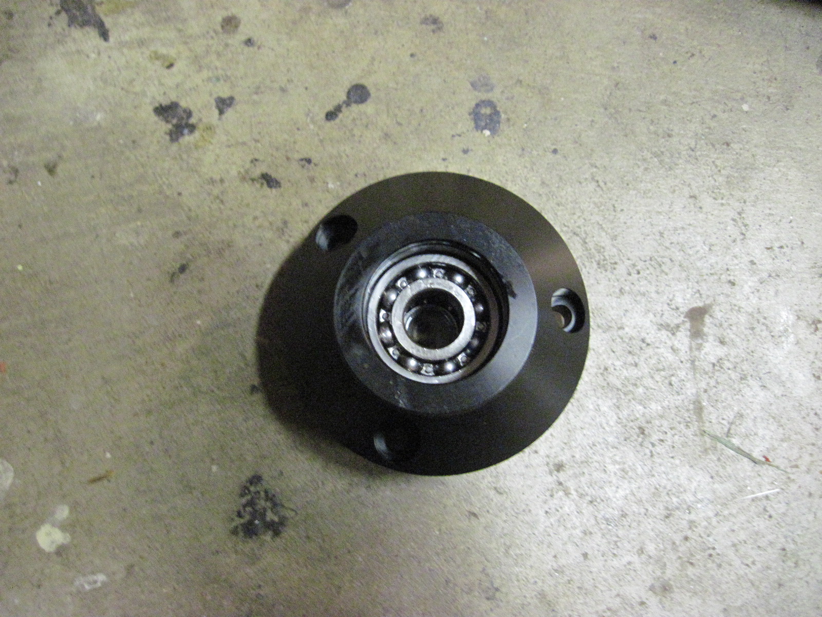


There are bearings on both sides of the pump cover and they are also held in with circlips.  An oil seal is then installed over the larger bearing and that is also held in by a circlip. Then the shaft is installed


Next, the rest of the pieces are installed on the shaft.  However woodruff keys are used to keep the inner rotors turning with the shaft and those needed lapping in order to remove small amounts of material so that they would fit in the slots on the shaft.  Per the instructions, I lapped them by spraying WD-40 on 600 grit sandpaper and moving the woodruff keys on the sand paper until they fit in their slots.

The pic on the left below shows the first inner rotor installed and the pic on the right shows the assembly with the first outer router installed along with the first scavenge port.


This process is repeated for a second time and here is a pic of the pump fully assembled.


However, after it was assembled then the gap between the scavenge ports and the rotors needed to be checked and if the clearence wasn't at lease .080mm (which it wasn't) then the ports needed to be lapped in a similar fashion to the woodruff keys.  It didn't take too long to do that and the gap was good after I reassembled it a 2nd time.  Set screws hold the scavenge pumps to the cartridge so that the only items that move are the rotors inside the cartridge

Ok, now it is time for the oil pan.  Here is a pic of the pan along with the packages holding the parts that will be installed.


After a couple of oil pan studs are installed in the block, the next items that are installed are two scavenge filter/strainers.  They aren't hard to install but you have to make sure that the o-rings don't get torn during the process.


The next items are a plug and an oil line fitting.


 And then the crank position sensor.


And then the locator dowels.


And finally the oil pan baffle plate followed by the seal for the oil pump inlet passage and the rear main seal (not pictured).


After putting rtv gasket silicone on the block, I was then able to install the oil pan.


And then it was time to install the oil scavenge pump into the oil pan.  The left pic shows where it goes and the right pic shows it installed.


I still need to install the pulley and the only item that I wasn't able to move from the stock pan to the new pan was the oil filter boss.  Unfortunately I can't find the jam nuts to allow me to unscrew the boss from the stock pan so I have put a call into HPD to see if I can get a couple of jam nuts sent to me.  It felt good to get the oil pan installed though!


Monday, October 3, 2011

Honda Fit Part 1

The Honda Fit Engine arrived last week -- which was very exciting!  Two other large boxes were supposed to arrive with the engine but the shipping company missplaced those but delivered them the next day.   Here is a pic of the engine in the back of the pick-up.  The engine is totally stock and a lot of the stuff comes off of it and is replaced with performance parts. 


The other two boxes hold the performance parts plus a bunch of other stuff.  Here is what I saw when I opened the first of the two boxes.


Honda Performance Development (HPD) really did a great job packaging everything and providing instructions.  It is a pleasure to deal with them!

Ok, time to start pulling stuff off of the motor!  The first things to come off were the oxygen sensor and the catalytic converter.


I also removed the EGR pipe which is the curvy pipe that went from the engine to the converter.  Once those were removed, I covered the holes with tape just to keep any unwanted stuff out of the engine.


The throttle body was next to come off. 


Next was the EGR Valve, the intake manifold chamber, and the intake runner.


 Now its time for the wiring harness.


And then the water outlet.


Everything up to this point was pretty easy to remove.  However, it is now time for the harmonic balancer which is secured with an extreme amount of torque on the nut. 


Several have had major problems getting this off.  I tried the my impact gun but to no avail.  I then put a breaker bar on it and hit it with a 5 pound hammer but I realized that the crankshaft was turning so that wasn't going to work.  So, I needed to keep the crankshaft from moving.  Honda has a special tool for this but I realized that I had a tool that I used with my FV to keep the flywheel (and thus the crankshaft) from moving.  Here is a pic of that tool installed.


So, I went back to hitting the breaker bar with the 5 lb hammer and sure enough it loosened up enough so that I could get it off with the impact gun.  I forgot to take a pic of it removed though. 

Next, I needed to prepare the engine for an engine stand so that I could turn the engine upside down and get the oil pan off.  The manual didn't mention this but I learned from Sean Maisey's blog that the starter, clutch, and flywheel needed to come off so they were next.


Finally time for the engine stand!  I didn't have one so I borrowed one from a friend of mine.  I first hoisted the engine up with my engine hoist.  You can see the engine stand in the background.


And here it is on the stand -- looks pretty good!


And finally it is time to remove the oil pan.  The oil pan doesn't have a gasket and is sealed with silicone.  The manual gave good instructions to hit it front and back with a rubber mallet until the tone changed.  It was then pretty easy to pry off at the pry points.


The oil pump pickup and the studs were also removed.  I don't have pictures of it but there are locating dowls in the oil pan.  One stayed with the block but the other one came off with the pan.  It was not easy to remove with out damaging it but a friend came over and he heated the area around the dowel with a torch while I pulled up on it with needle nose pliers until it just released. 

There was also a water outlet nipple that needed to be removed which required a lot of heat.  It was screwed into the head but was secured with a high strength thread sealent.  Once the around the nipple was hot enough I was able to unscrew it.  A plug that came in the kit was then installed.

Since a race engine does not need an Exhaust Gas Regulaator (EGR) valve or the EGR piple, plates are provided to block off those holes.  The one shown below if for the EGR pipe.


Now for one of the most challenging tasks.  The race engine also doesn't need a PCV valve so the PCV nipple installed in the intake runner is not necessary.  I used a punch to tap the PCV nipple out of the intake runner but the hole then needed to be plugged.  A plug is provided and then the intake runner needed to be heated to 248 degrees so that the metal would expand enough to accept the plug -- easier said than done!  It took a while to get the temperature of the runner up to 248 degrees.  I also didn't want to set my workbench, or any of the stuff on it, on fire so I did it on the concrete floor.


After it was hot enough, I was able to get the plug started but eventually it would only move about a millimeter even after I reaheated it back up to temperature after it cooled down.  I never did get it absolutely flush like the instructions said but I got it very close -- I don't think it is going to come out!!


And that is it for now!!  More complicated engine stuff to come in the next installment!


Sunday, September 25, 2011

Bodywork Part 4

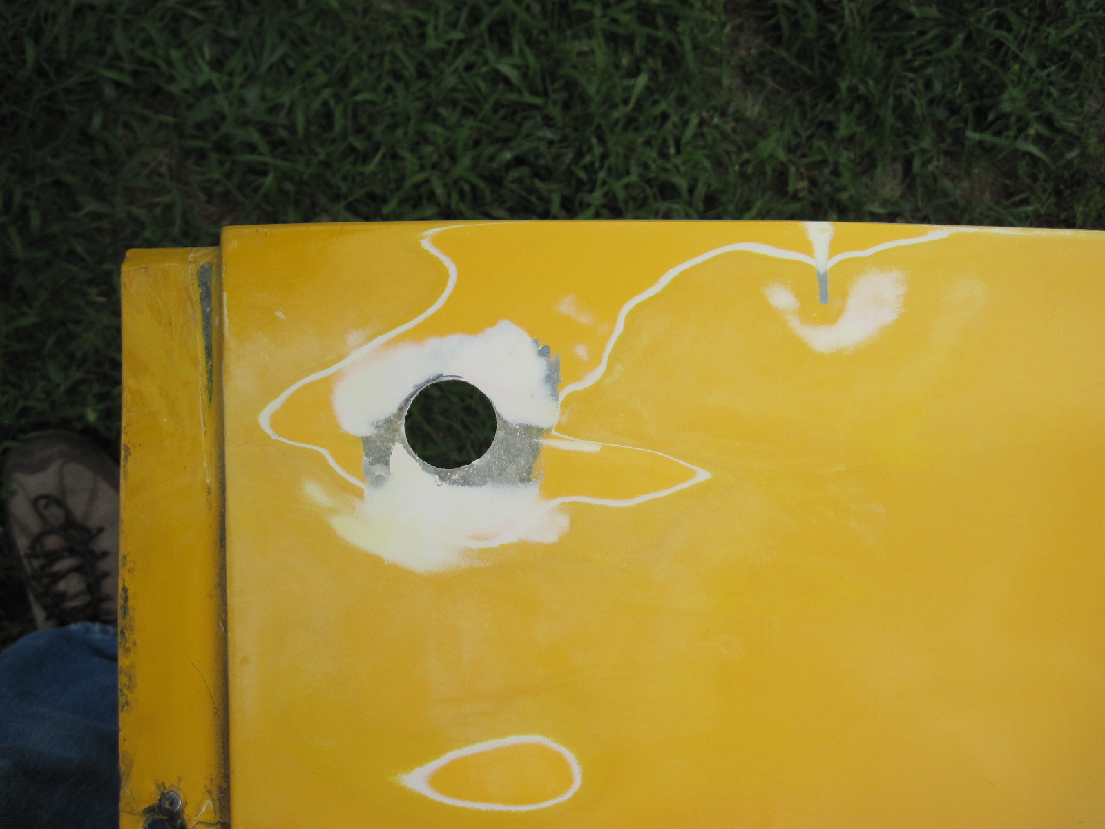
The bodywork continues and this weekend I switched to the cowling, at least I think that is what it is called.  The radio antenna mounts in it and it is the piece that fits over the dash and steering wheel.  There is a piece of copper that is on the underside that helps the radio work better and it was duct taped to the cowling but the duct tape was old and dryrotted so I decided to pop rivet it in place instead.  I used counter sunk rivets and then covered them with bondo so they wouldn't show.  Here are some pics.


That was an easy change.  The next one wasn't so easy -- and I'm still working on it.  On the right side of the car the gap between the cowling and the side panel is small and the way that it should be but on the right side the gap was too big in my opinion.


So, I started removing material where the two pieces meet.


After I removed about as much material as I felt comfortable with, I finally realized that I really needed to change the shape of the piece a little bit.  I needed to get the piece to flex a little bit so the best way to do that was to cut some slits in the piece which you can actually see in the picture on the right above.  But here is another pic.  You can also see the spider cracks in this piece which were most likely caused by forcing it to fit the way it should.  Getting fiberglass pieces to fit right can be very difficult!


By getting the piece to flex a little bit the gap has closed up nicely.  Of course, now I needed to permanently change the piece so that it fits right from now on.  So, I removed the gel coat on either side of the slits and taped the piece to the car and then fiberglassed over the slits.  The blue tape is just to protect the side panel from getting fiberglass resin on it.  I also fiberglassed the underside after the resin hardened.


The piece mounts to the chassis at the front and my changes to the left side of course changes how the hole lines up to the mounting point.  As you can see, the holes have been expanded quite a bit over the years so I took the opportunity to re-glass the piece and re-drill the holes.  I haven't finished that yet.


You can also see the piece of wood that is being used as a spacer on the cowling's right side (left picture above).  I will come up with something different but I haven't decided what yet.  

I have also been working on the nose and the shock cover but I haven't taken any pictures of them yet.  I haven't taken pictures of them because all I have been doing is repairing spider cracks. However, they aren't fitting the way I would like so I will be making some changes to those as well and will document those changes.

The engine kit was supposed to be delivered on Friday of last week but it was delayed and it should be delivered tomorrow (Monday).  Can't wait to see it!

Sunday, September 18, 2011

Bodywork Part 3

The weather was nice for doing bodywork so I was able to finish the right side panel.  Here are some before and after pics.


I'm also working on the nose and the shock cover but the HPD engine kit will be here this week so most of my attention will probably shift to that so that I can get the chassis and the engine to Eric Langbein.

Monday, September 5, 2011

Baltimore Grand Prix

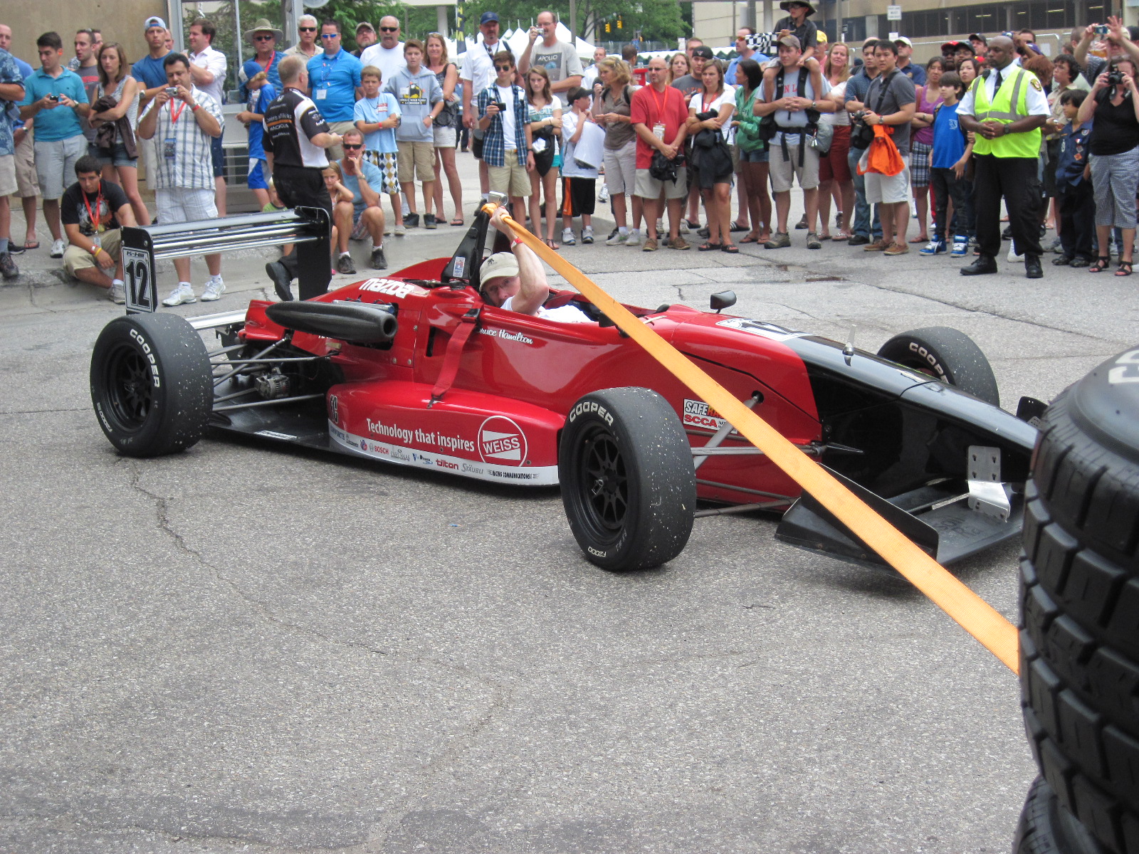
Well, I haven't gotten much work done on the car this weekend but I did spend the last three days at the Baltimore Grand Prix and ended up helping out Bruce Hamilton who was renting a USF2000 car from K-Hill Motorsports.  Eric Langbein was also there with his F2000 car and he did a great job in both races.  Here are some pics.


I am working on the right side panel of my car and will be posting before and after pics when I'm done with it.  The process is the same as I have shown for the left panel.  I also ordered the engine kit from HPD so hopefully I will have that by the end of September.